ADJUSTABLE – Frame Elevations

  • Saved as AutoCad 2010 files.

STEP 1: INSERT and EXPLODE the BLOCK you need into your drawing.
STEP 2: STRETCH as needed.
STEP 3: COPY the Rough Opening lines to the appropriate location and dimension as needed. (NOTE: The Rough Opening stretched with the elevation as it was being modified.)

    ADJUSTABLE FRAMES – Elevations

    Instructions for Adjustable Frames Elevations

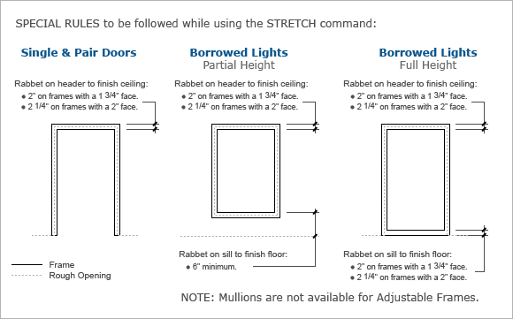
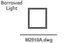
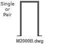
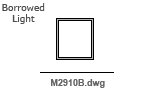
    Frame Elevations are drawn with a solid Polyline.

    Rough Openings are drawn with a dashed Polyline.

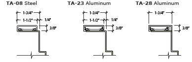
    FYI: Rough Openings are measured from the frame rabbet as follows:

    JAMBS – add 5/8" per side
    HEADS – add 13/16" above
    SILLS – add 7/16" below 

    ADJUSTABLE FRAMES – Elevations

    Elevations A – Frames with 1 3/4" face Timely ‘s casings that create a 1 3/4" frame face
    CAD Drawing for Elevations on Adjustable Door Frame CAD Drawing for Elevations on Adjustable Door Frame CAD Adjustable Elevations Casings that create 1_3 4in frame face
    CAD Download File Button CAD Download File Button
    Elevations B – Frames with 2" face Timely ‘s casings that create a 2" frame face
    CAD Drawing for Elevations on Adjustable Door Frame CAD Drawing for Elevations on Adjustable Door Frame CAD Adjustable Elevations Casings that create 1_3 4in frame face
    CAD Download File Button CAD Download File Button
    NOTE: The elevation’s “over all” dimensions must be manually modified for wood casings that do not result in either a 1 3/4" or 2" face.